Internet thinking Electronics Co., Ltd | Sign in | Registered account
  Enlish   繁體   日本語   German   中文
Open103V Package B  , STM32F1 Development Board SKU: Open103V Package B
  |  0 orders
Price
US $88.90 / PCS
Shipping
-->Arrival time 5-7 days
---->Arrival time 15-27 days
-->Arrival time 5-7 days
Quantity
 PCS
Parts Amount
US $88.90
 
Choose us! Escort for your needs!!!^_^
Data converter
Product Details
Part no.Open103V Package B
ManutacturerWaveshare
Date Code16+
Description-, STM32F1 Development Board SKU: Open103V Package B
 DatasheetCheck Datasheet
-
  • $88.99 
    $86.692+
    $85.193+
    $84.194+

    DESCRIPTION
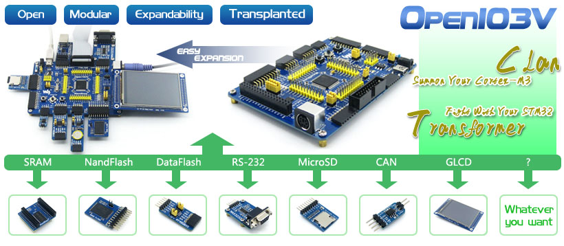
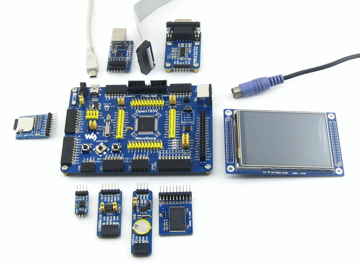
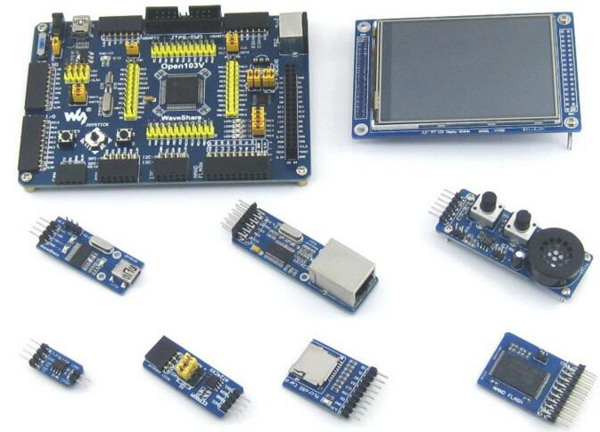
    STM32 development board designed for STM32F103V series, features the STM32F103VET6 MCU, and integrates various standard interfaces, pretty easy for peripheral expansions.
    STM32F103VET6 development board

    Overview

    Open103V is a STM32 development board that features a STM32F103VET6 device as the microcontroller. There are further expansions with various optional accessory boards for specific application. The modular and open design makes it the ideal for starting application development with STM32F family.


    What's On Board

    STM32F103VET6 development board on board resource
    1. STM32F103VET6:the high performance STM32 MCU in LQFP100 package which features
      • Core: ARM Cortex-M3 32-bit RISC;
      • Operating Frequency: 72MHz, 1.25 DMIPS/MHz;
      • I/Os: 80;
      • Operating Voltage: 2-3.6V;
      • Memories: 512K Flash, 64K RAM (the highest specification in STM32F103V series);
      • Communication Interfaces: 3xSPI, 5xUSART, 2xI2S, 2xI2C, 1xFSMC, 1xLCD, 1xSDIO, 1xUSB, 1xCAN;
      • AD & DA converters: 3xAD(12bit, 1μs, shares 16 channels); 2xDA(12bit);
      • Debugging/Programming: supports JTAG/SWD (serial wire debug) interfaces, supports IAP;
    2. 74LVC139: for FSMC expansion, makes it possible to connect multi peripherals through FSMC at the same time, such as connecting a LCD and a NAND FLASH;
    3. AMS1117-3.3: 3.3V voltage regulator;
    4. Power supply switch: 5V DC or USB;
    5. Power indicator;
    6. LEDs: Convenient for indicating I/O status or program debugging running state;
    7. Reset button;
    8. User key;
    9. Joystick: Convenient for I/O input (five positions);
    10. 32.768K crystal oscillator: used for internal RTC;
    11. 8M crystal oscillator: enables the MCU run at 72M frequency by frequency multiplication;
    12. SDIO Interface: connects to the Micro SD Board easily, It is much faster to read/write the Micro SD card via SDIO than via SPI;
    13. 8 I/O Interface: easily connects to keypad, motor, etc.;
    14. CAN Interface: communicates with accessory board which features the CAN device conveniently;
    15. SPI Interface: easily connects to SPI peripherals such as FLASH (AT45DBxx), SD card, MP3, etc.;
    16. I2C Interface: easily connects to I2C peripherals such as I/O expander(PCF8574), EEPROM (AT24Cxx), etc.;
    17. NAND FLASH Interface: easily connects to the NAND FLASH peripherals;
    18. LCD Interface: easily connects to the touch screen LCD;
    19. ONE-WIRE Interface: easily connects to ONE-WIRE devices (TO-92 package), such as temperature sensor (DS18B20), electronic registration number (DS2401), etc.
    20. PS/2 Interface: easily connects to PS/2 keyboard or mouse;
    21. USART1 Interface: easily connects to RS232, RS485, USB TO 232;
    22. USART2 Interface: easily connects to RS232, RS485, USB TO 232;
    23. USB Port: USB communication between board and PC;
    24. 5V DC jack;
    25. 5V/3.3 V power input/output;
    26. MCU pins connector: all the MCU pins are accessible on expansion connectors for further expansion;
    27. JTAG/SWD interface: for debugging/programming;
    28. Boot Mode Selection: for configuring the BOOT0 and BOOT1 pins;
    29. USB Enable Jumper
      • Short the jumper to enable the PC auto detection while USB connecting;
      • Open the jumper to disable;
    30. PS/2 Interface Jumper
      • Short the jumper to connect the PS/2 device to default I/Os;
      • Open the jumper to connect the PS/2 device to custom I/Os via DuPont wires;
    31. LEDs Jumper
      • Short the jumper to connect the LEDs to default I/Os;
      • Open the jumper to connect the LEDs to custom I/Os via DuPont wires;
    32. VBAT Selection Jumper
      • Short the jumper to use system power supply;
      • Open the jumper to connect the VBAT to external power, such as battery;

    Photos

    STM32 Development Board
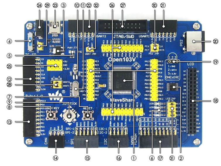
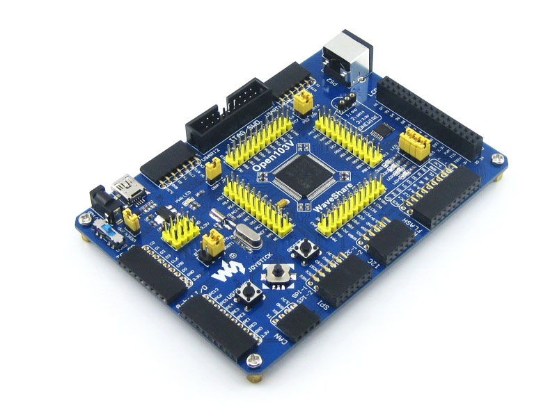
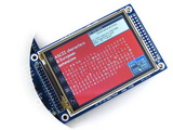
    Open103V Development Board
    STM32 Development Board
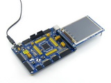
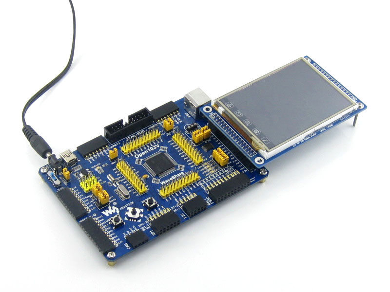
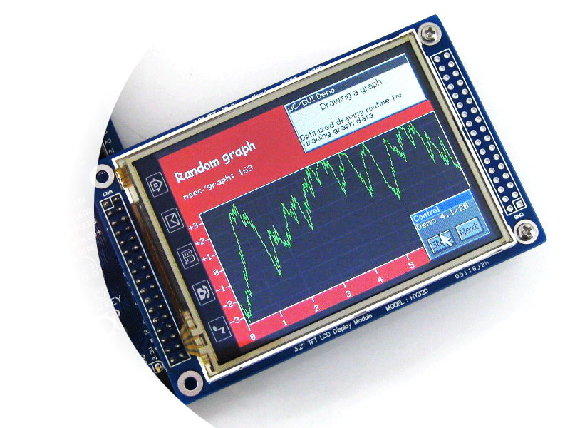
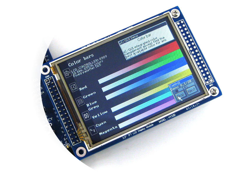
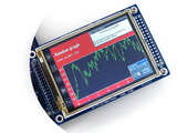
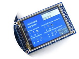
    Connecting to touch screen LCD
    STM32 Development Board
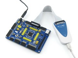
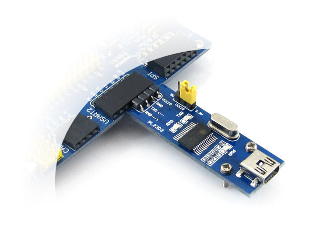
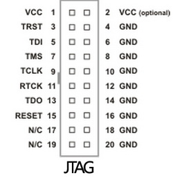
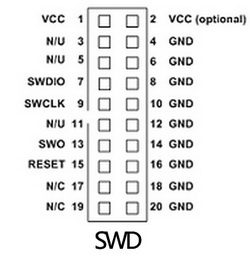
    Connecting to ST-LINK
    STM32 Development Board
    Connecting to various peripherals

    Open103V μC/OS-II (Ⅰ)
    Open103V-ucosii
    Open103V μC/OS-II (Ⅱ)
    Open103V-ucosii
    Open103V μC/OS-II (Ⅲ)
    Open103V-ucosii
    Open103V μC/OS-II (Ⅳ)
    RS232 Board
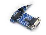
    Connecting to RS232 Board via USART
    PL2303 USB UART Board mini
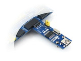
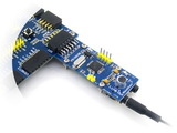
    Connecting to USB UART Board via USART
    SN65HVD230-CAN-Board
    Connecting to CAN Board via CAN
    ENC28J60 Ethernet Board
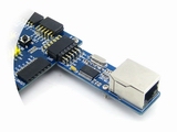
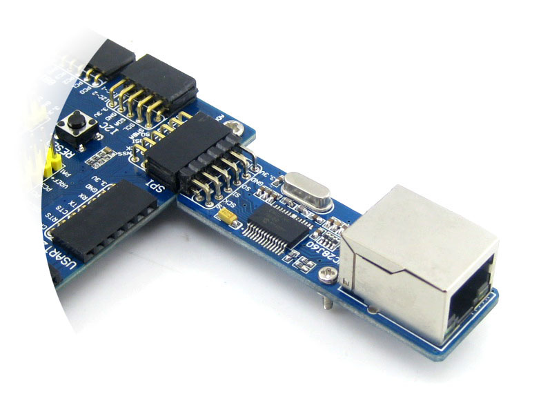
    Connecting to Ethernet Board via SPI
    SL811 USB Board
    Connecting to SL811 USB Board via FSMC
    VS1003B MP3 Board
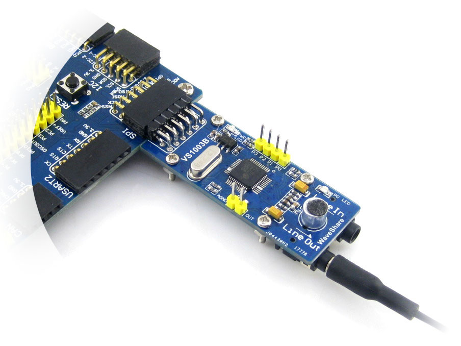
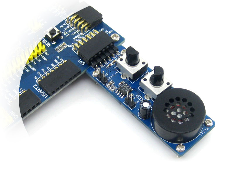
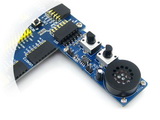
    Connecting to VS1003B MP3 Board via SPI
    NRF24L01 RF Board
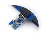
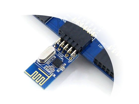
    Connecting to NRF24L01 RF Board via SPI
    8 Push Buttons
    8 Push Buttons on the 8Bit I/O
    4x4 Keypad
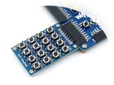
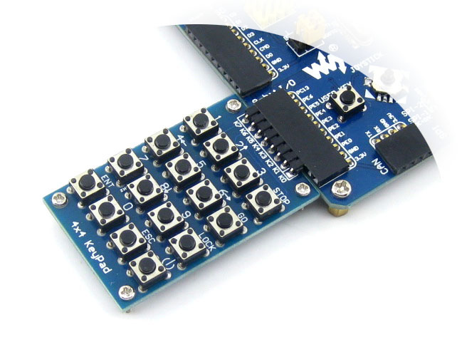
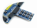
    4x4 Keypad on the 8Bit I/O
    Analog Test Board
    Test Board on the AD/DA port
    AT24CXX EEPROM Board
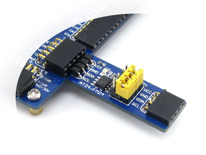
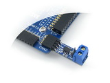
    Connecting to EEPROM Board via I2C
    I2C cascading x3
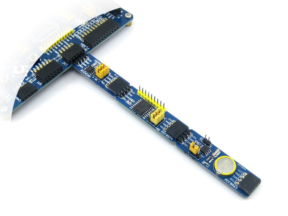
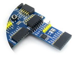
    Multi I2C peripheral Module connected to the I2C bus
    AT45DBXX-DataFlash-Board
    Connecting to DataFlash Board via SPI
    Micro-SD-Storage-Board
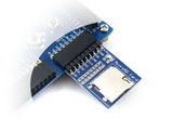
    Connecting to Micro SD Board via SDIO
    NandFlash-Board-A
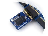
    Connecting to NandFlash Board via FSMC
    Connecting to any accessory board
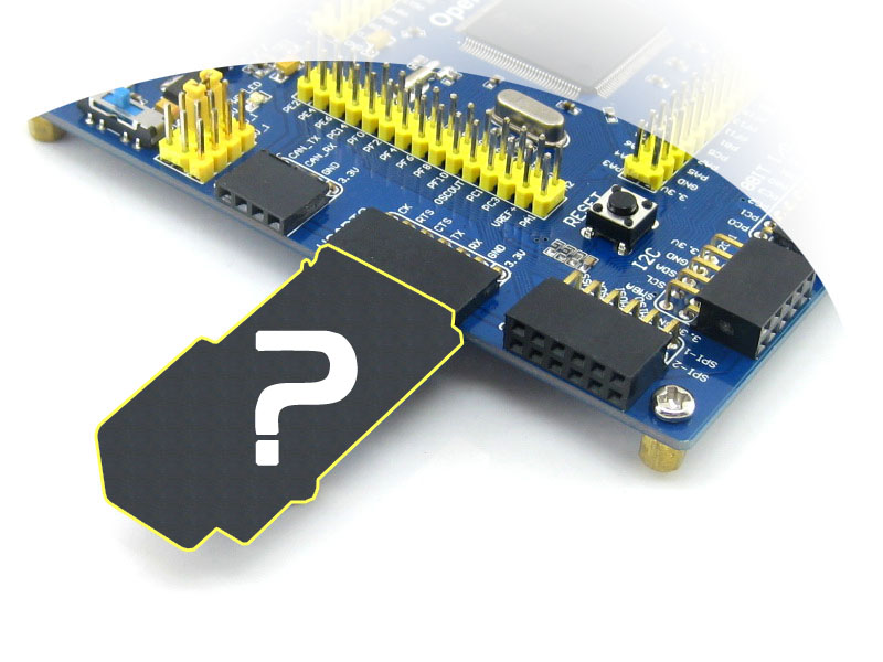
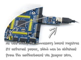
    Connecting to any accessory board you need

    Note: 
    The Open103V supports programming via STM32 USART bootloader, a USB TO UART accessory board is also provided in the package. 
    The Open103V does NOT integrate any debugging function, a debugger is required.


    JTAG/SWD Interfaces

    The figure 1, and 2 show the header pinouts of JTAG/SWD interface

    Figure 1. JTAG Header Pinout
    JTAG Header Pinout
    Figure 2. SWD Header Pinout
    SWD Header Pinout

    Development Resources

    • Related softwares (KEIL etc.)
    • Demo Code (examples in C, μC/OS-II)
    • Schematic (PDF)
    • STM32 Development documents (Datasheet etc.)

    Wiki: www.waveshare.com/wiki/Open103V

$ 70.90 (USD)/PCS
$ 88.90 (USD)/PCS


www.int-thinking.net © 2006-2017 Internet Thinking(Hong Kong) Electronic Co.,Limited(Copyright)